
A reinforced concrete beam is designed as a two-span beam with a cantilever. The cross-section varies along the length of the cantilever (tapered cross-section). The internal forces, the required longitudinal and shear reinforcement for the ultimate limit state are calculated.

In this example, the shear at the interface between concrete cast at different times and the corresponding reinforcement are determined according to DIN EN 1992-1-1. The obtained results with RFEM 6 will be compared to the hand calculation below.
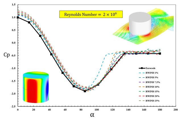
The available standards, such as EN 1991-1-4 [1], ASCE/SEI 7-16, and NBC 2015 presented wind load parameters such as wind pressure coefficient (Cp) for basic shapes. The important point is how to calculate wind load parameters faster and more accurately rather than working on time-consuming as well as sometimes complicated formulas in standards.
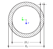
Determine the torsional constant for the cross-section of the tube (annular area) analytically, and compare the results with the numerical solution in RFEM 5 and RSTAB 8 for various wall thicknesses.
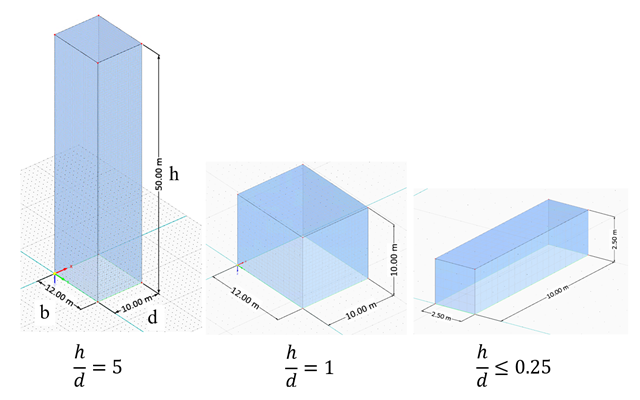
In the current validation example, we investigate wind force coefficient (Cf) of cube shapes with EN 1991-1-4 [1]. There are three dimensional cases that we will explain more about if in the next part.

The model is based on the example 4 of [1]: Point-supported slab.
The flat slab of an office building with crack-sensitive lightweight walls is to be designed. Inner, border and corner panels are to be investigated. The columns and the flat slab are monolithically joined. The edge and corner columns are placed flush with the edge of the slab. The axes of the columns form a square grid. It is a rigid system (building stiffened with shear walls).
The office building has 5 floors with a floor height of 3.000 m. The environmental conditions to be assumed are defined as "closed interior spaces". There are predominantly static actions.
The focus of this example is to determine the slab moments and the required reinforcement above the columns under full load.
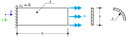
A thin plate is fixed on one side and loaded by means of distributed torque on the other side. First, the plate is modeled as a planar plate. Furthermore, the plate is modeled as one-fourth of the cylinder surface. The width of the planar model is equal to the length of one-fourth of the circumference of the curved model. The curved model thus has almost equal torsional constant to the planar model.
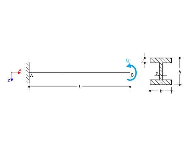
A cantilever of I-profile is supported on the left end and it is loaded by the torque M. The aim of this example is to compare the fixed support with the fork support and to investigate the behaviour of some representative quantities. The comparison with the solution by means of plates is also made. The verification example is based on the example introduced by Gensichen and Lumpe.
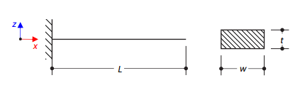
A steel cantilever with a rectangular cross‑section is fully fixed on one side and free on the other. The aim of this verification example is to determine the natural frequencies of the structure.
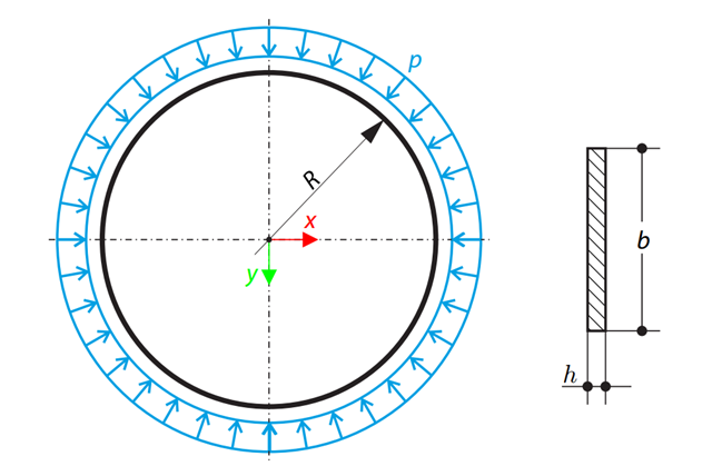
A thin circular ring of a rectangular cross-section is exposed to external pressure. Determine the critical load and corresponding load factor for in-plane buckling.

In the current validation example, we investigate wind pressure value for both general structural designs (Cp,10) and cladding or façade design (Cp,1) of rectangular plan buildings with EN 1991-1-4 [1]. There are three dimensional cases that we will explain more about if in the next part.
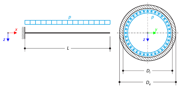
A pipe with a tubular cross-section is loaded by internal pressure. This internal pressure causes axial deformation of the pipe (the Bourdon effect). Determine the axial deformation of the pipe endpoint.
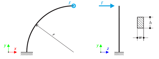
A quarter-circle beam with a rectangular cross-section is loaded by means of an out-of-plane force. This force causes a bending moment, torsional moment, and transverse force. While neglecting self-weight, determine the total deflection of the curved beam.
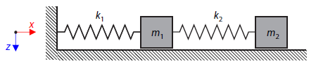
A double-mass oscillator consists of two linear springs and masses, which are concentrated at the nodes. The self-weight of the springs is neglected. Determine the natural frequencies of the system.
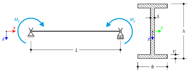
A simply supported beam is loaded by pure bending. Determine the critical load and corresponding load factor due to lateral buckling.
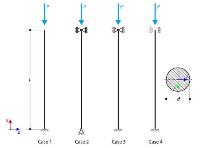
A strut with a circular cross-section is supported according to four basic cases of Euler buckling and subjected to pressure force. Determine the critical load.
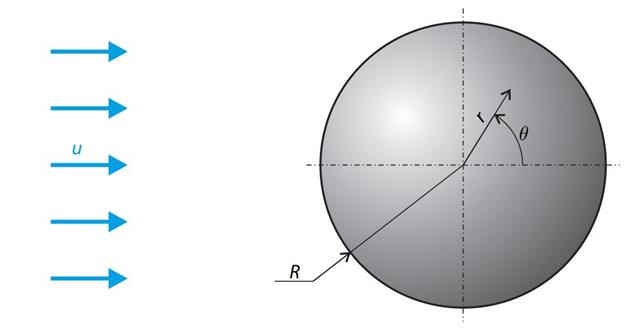
A sphere is subjected to a uniform flow of viscous fluid. The velocity of the fluid is considered at infinity. The goal is to determine the drag force. The parameters of the problem are set so that the Reynolds number is small and the radius of the sphere is also small, thus the theoretical solution can be reached - Stokes flow (G. G. Stokes 1851).

A column is composed of a concrete section (rectangle 100/200) and a steel section (profile I 200). It is subjected to pressure force. Determine the critical load and corresponding load factor. The theoretical solution is based on the buckling of a simple beam. In this case, two regions have to be taken into account due to different moments of inertia and material properties.
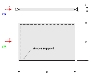
A rectangular steel plate of dimensions is simply supported at its edges. Determine the natural frequencies of the rectangular plate.
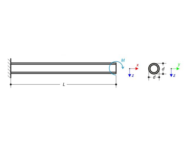
A cantilever is loaded by a moment at its free end. Using the geometrically linear analysis and large deformation analysis, and neglecting the beam's self-weight, determine the maximum deflections at the free end. The verification example is based on the example introduced by Gensichen and Lumpe.
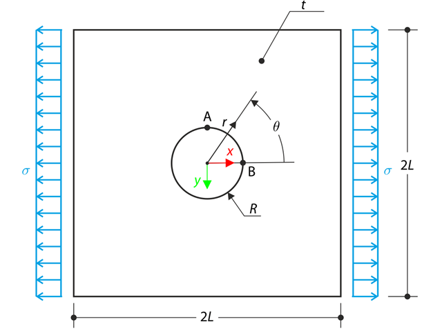
The wide plate with a hole is loaded in one direction by means of the tensile stress σ. The plate width is large with respect to the hole radius and it is very thin, considering the state of the plane stress. Determine the radial stress σr, tangential stress σθ, and shear stress τrθ around the hole.
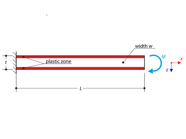
A cantilever is fully fixed on the left end and subjected to a bending moment considering plasticity.
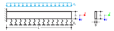
A cantilever from a rectangular cross-section is lying on an elastic Winkler foundation and loaded by distributed loading. The image shows the calculation of the maximum deflection and maximum bending moment.
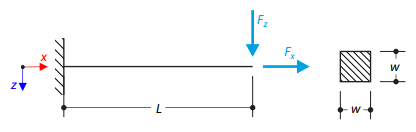
A cantilever is loaded by a transversal and an axial force on the right end and is fully fixed on the left end. The problem is described by the following set of parameters. The problem is solved by using the geometrically linear analysis, second-order analysis, and large deformation analysis.
A cantilever is loaded by a moment at its free end. Using the geometrically linear analysis and large deformation analysis, and neglecting the beam's self-weight, determine the maximum deflections at the free end. The verification example is based on the example introduced by Gensichen and Lumpe.
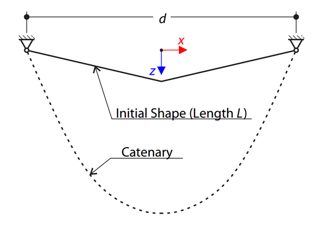
A very stiff cable is suspended between two supports. Determine the equilibrium shape of the cable (the catenary), consider the gravitational acceleration, and neglect the stiffness of the cable. Verify the position of the cable at the given test points.

In the current validation example, we investigate wind pressure coefficient (Cp) of flat roof and walls with ASCE7-22 [1]. In the section 28.3 (Wind loads - main wind force resisting system) and Figure 28.3-1 (load case 1), there is a table which shows Cp value for different roof angle.
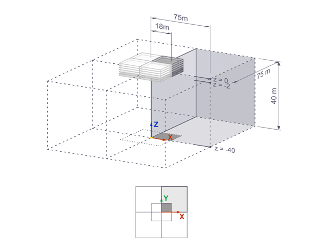
The settlements of a rigid square foundation on a lacustrine clay [1] are calculated with RFEM. One quarter of the foundation is modelled. The foundation has a width of 75.0 m in both sides. Construction stages are used to generate the results.
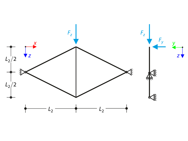
Planar truss consisting of four sloped members and one vertical member is loaded at the upper node by means of the vertical force Fz and out of plane force Fy. Assuming large deformation analysis and neglecting self-weight, determine the normal forces of the members and the out of plane displacement of the upper node uy. The verification example is based on the example introduced by Gensichen and Lumpe.

An inner column in the first floor of a three-story building is designed. The column is monolithic connected with the top and bottom beams. The fire design simplified method A for columns according to EC2-1-2 is than proofed and the results compared to [1].